The basic course by André Bakker.
About buoyantPressure in OpenFoam
buoyantPressure Sets fixedGradient pressure based on the atmospheric pressure gradient
|
1 2 3 4 5 |
due to the nature of the PISO-algorithm used in interFoam, it is necessary to have a very "good" pressure field, as the pressure field is required in the velocity correction step of the scheme in order to reach mass conservation (i.e.div(U)=0). If you look at the PISO-algorithm you will see that this means if the flux is zero (as it is orthogonal to the wall) it is necessary that the second derivative of pressure (orthogonal to the wall) must be zero, too (in areas where the density is constant). buoyantPressure fulfills this requirement in areas of constant VOF-function / density. I'm not sure about mass conservation if sloped walls touch areas with VOF-values 0<VOF<1. |
http://www.openfoam.org/docs/user/boundaries.php
http://www.cfd-online.com/Forums/openfoam/67155-interfoam-mass-conservation.html
I got this error today: wrong token type – expected scalar found on line 3 the word ‘nan’
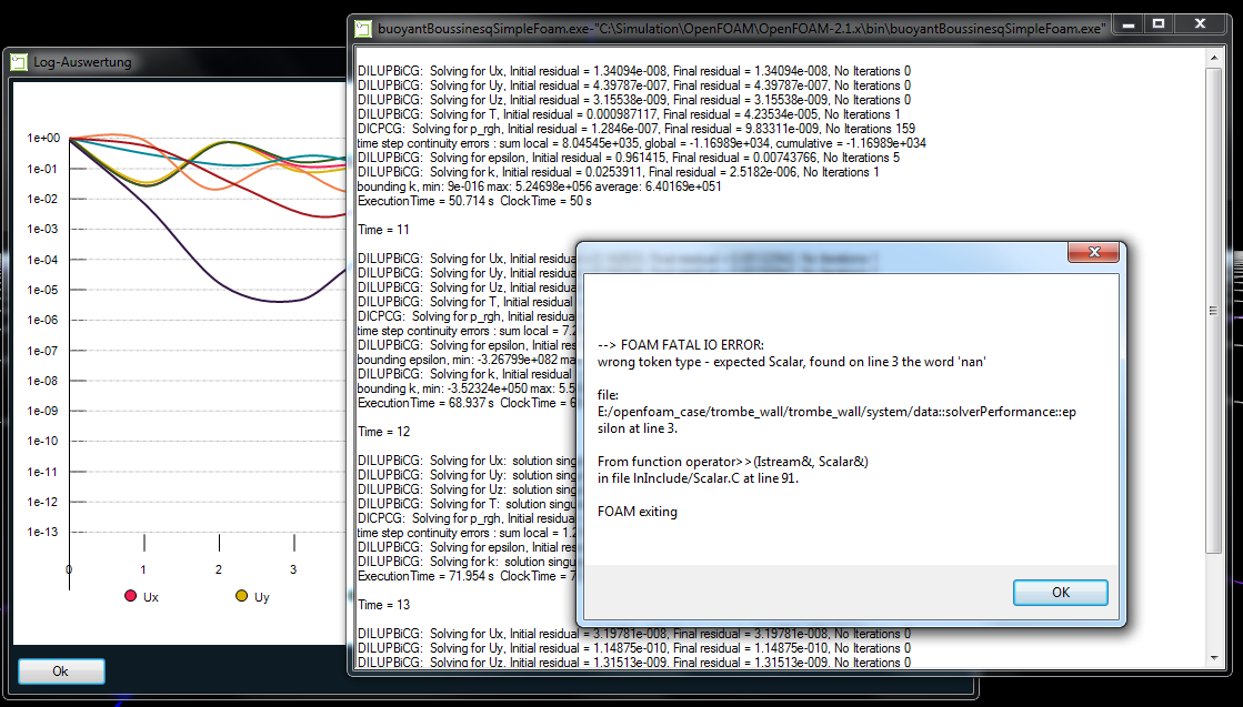
I see it,
if I give k & epsilon the initial value of 0;
if there is not at least one patch with buoyantPressure
How to create new component for TRNSYS 17
the basic is desribed in TRNSYS 17 Manual Volumen 1 Getting Started in 1.8. Creating a new component. The problem is, the tutorial was created for a long time, something changed since the Visual Studio .NET 2003 is not availble. When Visual Studio 2003 was used, the TRNSYS Studio compiles the DLL file directly and save them to the UserLib folder. Now, without Visual Studio 2003, you get a notification, and get two file exported. One .cpp file(C++ source file) and one .dsp(project description for Visual Studio). If you have new generation Visual Studio installed, then open the .dsp file with it, then a new .vcxproj file will be created as project desription file for the new Visual Studio – I use Visual Studio Express 2012. Then build the DLL is quite easy. If TRNSYS.h is not found, copy it form “Trnsys17\Compilers\Cpp-Mvs2003\Include”.
actually I wanna do it with MingW and Code::Blocks, somehow I cannot get it working, I will try later. The .dsp file has some configurations for the compiler and Code::Blocks cannot read it properly, I think. If someone knows how it works, please let me know.
The data structure of Type 56(Multi-zone) in TRNSYS
|
1 2 3 4 5 6 7 |
The following three TYPE 56 standard files are generated automatically every time the BUI file is saved: <ul> <li>a file containing all information about the building excluding the wall construction (*.BLD) and</li> <li>another file that contains the ASHRAE transfer functions for the walls (*.TRN).</li> <li>In addition, an information file (*.INF) is generated as log file which needs to be checked for error messages. The information file contains the processed BUI file followed by the values of wall transfer function coefficients, the overall heat transfer conductance U and the related Uvalue. This information may be useful for the user in verifying the wall description data. Next, the list of inputs required for the Type 56 is printed. These will most commonly be outputs of other components in the TRNSYS simulation. Also, the information file (*.INF) provides a list of outputs of Type 56 as selected by the user. These outputs may be inputs to other components. Finally, a brief table with all of the wall types and their U-values is printed to the information file.</li> </ul> The *.BLD and *.TRN files are used by TYPE 56 during the simulation process. The generated files get the name as the opened *.BUI file and are located in the same directory. If an error occurs, no files are generated. A window displays for detailed information on the error. |
It looks like if I want to use the Heat Tansfer Coefficient based on the results from OpenFoam, I need modify the .inf file somehow. The Heat Transfer Coefficient depends on the Wall Surface Temperatue and the Air Temperature close to the wall. Usually, the convective heat transfer coefficient of wall is set per wall type either as userdefined or as internal calculation. During the internal calculation, the AirNode temperature is used, which will be replaced by OpenFoam in the Coupling. So, I think we should choose it as userdefined. Under userdefined dialog, we can see 3 options: Constant Value, Input, Schedule. Input should be the right choice, which means the convective heat transfer coefficient of each wall are defined as input for Type56. We can calculate them and save data in an external file. Because of the variation of the Air Temperature in CFD, the Heat Transfer Coefficient could also be variable. That means, for each surface of the geometry, a wall type should be defined according to the air temperature. 
|
1 2 3 |
from 05-MultizoneBuilding.pdf page 5-121 Type 56 also offers the possibility to define a certain energy flux to a certain wall surface. |
I searched whole day without success, the workflow is to use the heat flux value from OpenFoam for surface energy balance calculation instead of the process of internal calculation with airnode temperature. If Fluent is used, maybe Type 101 is just right for this, but OpenFoam is the tool available to me. I must find another solution to make this happen. I don’t really understand the setting of Wall Gain , is this just means Convective Heat Flux?
the ES-CFD-Coupling design scheme
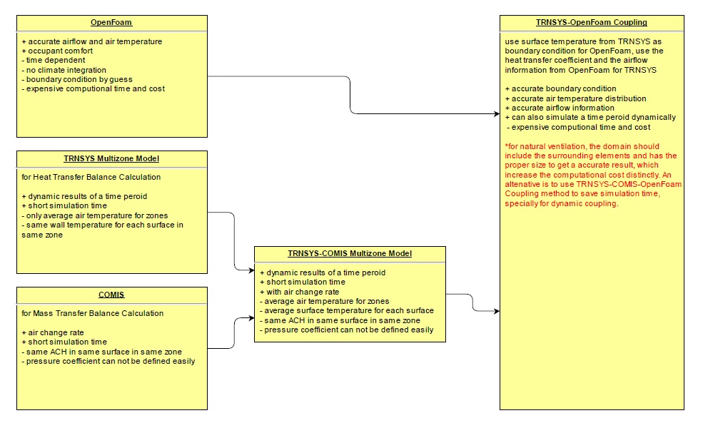
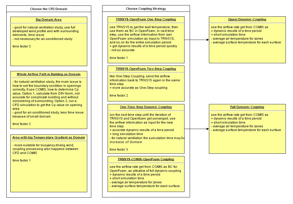

Integration of Building Energy and Airflow Simulation
Why?
|
1 2 3 4 5 6 7 8 9 10 11 12 13 14 15 16 17 18 19 20 21 22 23 |
Energy Simulation Pros: <ul> <li>dynamic</li> <li>quick</li> </ul> Cons: <ul> <li>Most ES programs assume the indoor air is completely mixed and with uniform properties. This may not be true for most buildings.</li> <li>ES programs do not solve the air movement and contaminant transportation in the space.</li> </ul> CFD Pros: <ul> <li>detailed time-dependent and spatial distribution of many parameters</li> <li>accurate indoor air velocity and temperature distributions</li> </ul> Cons: <ul> <li>needs a lot of computation time</li> </ul> |
Benefit
- The indoor air temperature gradient and covective heat transfer from CFD can used in an ES model for more accurate energy calculation.
- CFD can accurately simulate natural ventilation driven by wind effect and stack effect, that can also be used in ES model.
- ES can provide more accurate flow and thermal boundary conditions for CFD simulation
CFD can also be exteneded to solve heat transfer in solid material, even with an appropriate radiation model, HVAC system model, and plant model, the extended CFD program can have the functions of both ES and CFD programs. But it is very eompztationally expensive.